INTRODUCTION
3D imaging in machine vision is a rapidly developing technology that gives accurate images of three-dimensional objects for inspection, measurement etc. There are multiple ways to implement a 3D imaging system; it can be based on stereo imaging, time of flight of a laser or laser triangulation. Laser triangulation is a widely used method that pairs a laser and a camera to produce 3D images of objects.
PRINCIPLE
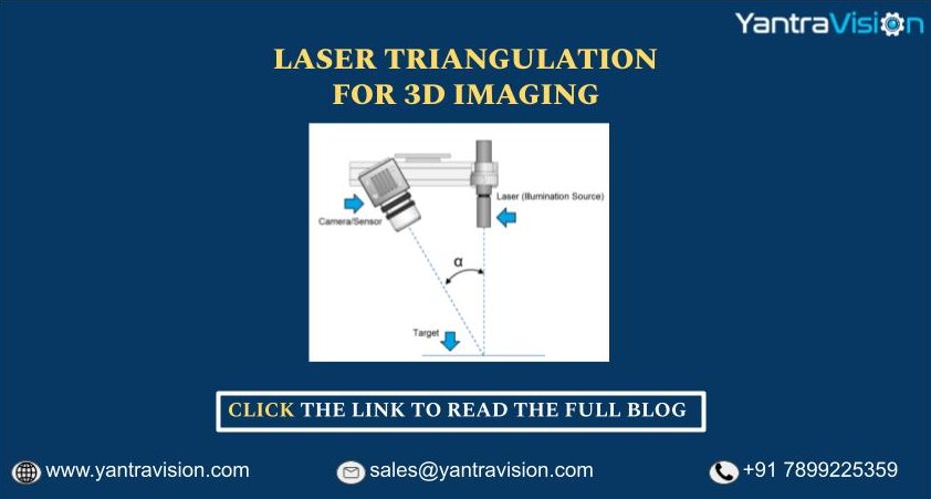
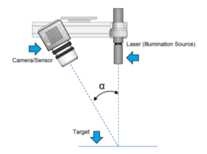
The laser and the camera are aimed at the object with a known offset angle between them, as shown in the image below.
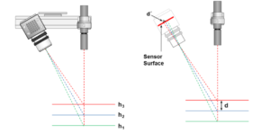
The laser light reflects back to the sensor at a particular angle after striking the surface. This angle varies with the object depth, and the reflected light strikes the sensor at different locations depending on that angle. The location at which the laser strikes the sensor is proportional to the object from the sensor, and knowing this location is enough to obtain the depth information of the object. The systems generally use a diode laser along with a CCD or CMOS area scan sensor.
A line laser projects an entire line on the object to obtain its cross-section and with the addition of 1D motion, the system can append all the cross-sections to generate a 3D surface map of the object. The system incorporates memory buffers to store multiple such scans and generate a complete 3D image of the object, which is represented as a 16-bit heightmap.
FACTORS TO CONSIDER
Measuring with increased precision:
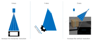
High precision measurement is an important requirement for most industrial applications of 3D laser triangulation. The precision along the 3 axes can be increased in the following ways:
- X-axis: Increasing the resolution along the x-axis is a trivial matter, as it only requires increasing the horizontal resolution of the camera.
- Z-axis: Similarly, increasing the resolution along the z-axis requires increasing the vertical resolution of the camera.
- Y-axis: The case of y-axis is slightly different. Here, the resolution depends on the fps of the camera and the speed of the object, so increasing the resolution requires increasing the fps of the camera or decreasing the object speed.
Increasing the range:
An increased range enables the system to capture images of objects of larger dimensions, which improves the overall capability of the system. However, there is an inherent tradeoff between range and resolution, as increasing the range would reduce the resolution of the system and vice versa.
The angle between sensor and laser:
The angle between the sensor and laser is another factor that affects the range and resolution tradeoff. A larger angle would create a larger profile of the object on the sensor, which would result in a higher resolution but limit the range of the system. A smaller angle would create a smaller profile, which would increase the range but limit the resolution of the system.
COMPARISON OF COMPACT AND DISCRETE SYSTEMS
There are multiple options when it comes to setting up a laser triangulation system. It could be a discrete setup with the camera, lighting, and processor assembled from separate components, or it could be a compact 3D sensor, where all the components are bundled together as a complete solution.
Many applications can be solved using a 3D compact sensor. They offer tremendous benefits when it comes to component protection, calibration precision, maintenance effort etc. However, they offer very little customization and flexibility.
A discrete setup is more expensive to put together and requires a lot more effort for maintenance and support. However, they prove to be a much better solution for applications with certain specific requirements which might need flexibility in terms of the working distance, the resolution of the camera and the algorithms that can be implemented on the hardware.
A discrete setup is much better suited for edge-case applications. A high-resolution camera along with an FPGA can meet the requirements of even the most demanding applications. It can be used for many 3D imaging applications like tire inspection, steel beam inspection, wood thickness measurement etc.
| COMPACT | DISCRETE |
|
|
FPGA FOR LASER TRIANGULATION
As mentioned previously, 3D imaging systems use a laser line and a camera with the addition of 1D motion to image cross-sections of the object and then append those cross-sections to generate a 3D surface map. This process generates a large amount of data and requires complex image processing to produce a complete 3D image for further analysis. The applications for this method also typically have real-time requirements, which makes the implementation challenging and resource-intensive.
An FPGA can reliably process a high bandwidth of data with very low cycle time, making them well suited to implement the typical algorithms used in such systems. The combination of parallel computation, dedicated computational resources like multipliers and RAM blocks offer a complete set of resources for real-time image processing algorithms like edge detection, filtering, line detection etc. Moreover, an FPGA has enough computational resources to perform handle operations like I/O, motion control etc.
YANTRAVISION OFFERING
The Mikrotron Eosens Creation series offers an open FPGA platform along with the camera that can be used to implement the algorithms for the 3D imaging system. It removes the need of using an external processor and reduces the total system cost. We are preferred technology partners of Mikrotron and have the capability to implement custom IPs on their open FPGA platform as per the requirements of the application.


